Plano-Convex lenses have positive focal lengths, converge incident light, and from both real images(as might be focused in a piece of paper), and virtual images(as are seen through the lenses when they are used as magnifiers).They are widely used in telescopes, collimators, optical transceivers, magnifiers, radiometers and condensers.
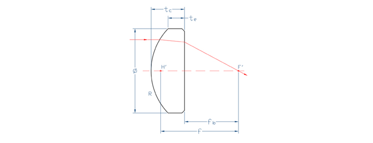
| Specifications | |
| Material | BK7 or UV Fused Silica |
| Diameter Tolerance | +0.0, -0.1mm |
| Center Thickness Tolerance | +/-0.1mm |
| Paraxial Focal Length | +/-0.5% |
| Clear Aperture | >90% |
| Surface Quality | 40-20 S/D |
| Surface Figure | λ/8@632.8nm |
| Contration | 1 arc min |
| Coating | Single Layer MgF2 or "V"AR coating |
BK7 Pl-cx Lenses
| Part Number | Φ | R | Tc | Te | EFL |
| PCX-063-R065 | 6.35 | 6.56 | 3.819 | 3 | 12.7 |
| PCX-063-R131 | 6.35 | 13.118 | 3.39 | 3 | 25.7 |
| PCX-063-R165 | 6.35 | 16.53 | 3.308 | 3 | 31.8 |
| PCX-063-R196 | 6.35 | 19.670 | 3.258 | 3 | 38.1 |
| PCX-127-R131 | 12.7 | 13.118 | 5.330 | 3 | 25.4 |
| PCX-127-R196 | 12.7 | 19.670 | 4.052 | 3 | 38.1 |
| PCX-127-R258 | 12.7 | 25.589 | 3.789 | 3 | 50.2 |
| PCX-127-R391 | 12.7 | 39.170 | 3.519 | 3 | 75.6 |
| PCX-127-R515 | 12.7 | 51.520 | 3.392 | 3 | 100 |
| PCX-127-R774 | 12.7 | 77.450 | 3.251 | 3 | 150 |
| PCX-254-R131 | 25.4 | 13.118 | 12.807 | 3 | 25.4 |
| PCX-254-R2584 | 25.4 | 25.589 | 6.321 | 3 | 50.2 |
| PCX-254-R391 | 25.4 | 39.170 | 5.122 | 3 | 75.6 |
| PCX-254-R515 | 25.4 | 51.520 | 4.585 | 3 | 100 |
| PCX-254-R774 | 25.4 | 77.450 | 4.047 | 3 | 150 |
| PCX-254-R1035 | 25.4 | 103.510 | 3.783 | 3 | 200 |
| PCX-254-R1290 | 25.4 | 129.060 | 3.626 | 3 | 250 |
| PCX-254-R1550 | 25.4 | 155.040 | 3.521 | 3 | 300 |
| PCX-254-R2061 | 25.4 | 206.100 | 3.390 | 3 | 400 |
| PCX-254-R2594 | 25.4 | 259.400 | 3.312 | 3 | 500 |
| PCX-254-R3873 | 25.4 | 389.206 | 3.208 | 3 | 750 |
| PCX-254-R5176 | 25.4 | 517.600 | 3.156 | 3 | 1000 |
| PCX-508-R515 | 50.8 | 51.520 | 9.673 | 3 | 100 |
| PCX-508-R774 | 50.8 | 77.450 | 7.279 | 3 | 150 |
| PCX-508-R1035 | 50.8 | 103.510 | 6.170 | 3 | 200 |
| PCX-508-R1290 | 50.8 | 129.060 | 5.521 | 3 | 250 |
| PCX-508-R1550 | 50.8 | 155.040 | 5.509 | 3 | 300 |
| PCX-508-R2061 | 50.8 | 206.100 | 4.566 | 3 | 400 |
| PCX-508-R2594 | 50.8 | 259.400 | 4.251 | 3 | 500 |
| PCX-508-R3873 | 50.8 | 387.300 | 3.833 | 3 | 750 |
| PCX-508-R5176 | 50.8 | 517.600 | 3.625 | 3 | 1000 |
Like Plano-convex lens, double convex lenses have positive focal lengths and form both real and virtual images. Symmetry is assured by finishing both surfaces with the same tool. Because of symmetry, aberrations including coma, distortion and lateral chromatic aberration almost exactly canceled at unit conjugate radio. Double convex lenses have shorter focal lengths than Plano-convex lenses of equal diameter and surface radius.
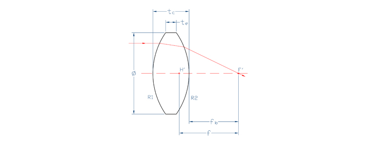
| Specifications | |
| Material | BK7 or UV Fused Silica |
| BK7 or UV Fused Silica | +0.0, -0.1mm |
| Center Thickness Tolerance | +/-0.1mm |
| Paraxial Focal Length | +/-0.5% |
| Clear Aperture | >90% |
| Surface Quality | 40-20 S/D |
| Contration | 1 arc min |
| Coating | Single Layer MgF2 or "V"AR coating |
BK7 Bi-cx Lenses
| Part Number | Φ | R | Tc | Te | EFL |
| DCX-063-R056 | 6.35 | 5.619 | 4.960 | 3 | 6.4 |
| DCX-063-R124 | 6.35 | 12.400 | 3.820 | 3 | 12.7 |
| DCX-063-R190 | 6.35 | 19.055 | 3.530 | 3 | 19 |
| DCX-063-R257 | 6.35 | 25.700 | 3.390 | 3 | 25.4 |
| DCX-127-R118 | 12.7 | 11.800 | 6.680 | 3 | 12.7 |
| DCX-127-R186 | 12.7 | 18.664 | 5.220 | 3 | 19 |
| DCX-127-R255 | 12.7 | 25.500 | 4.610 | 3 | 25.4 |
| DCX-127-R387 | 12.7 | 38.730 | 4.050 | 3 | 38.1 |
| DCX-127-R512 | 12.7 | 51.290 | 3.790 | 3 | 50.2 |
| DCX-127-R643 | 12.7 | 64.392 | 3.628 | 3 | 62.9 |
| DCX-127-R774 | 12.7 | 77.450 | 3.521 | 3 | 75.6 |
| DCX-254-R167 | 25.4 | 16.760 | 14.725 | 3 | 19 |
| DCX-254-R243 | 25.4 | 24.380 | 10.132 | 3 | 25.4 |
| DCX-254-R381 | 25.4 | 38.110 | 7.360 | 3 | 38.1 |
| DCX-254-R508 | 25.4 | 50.820 | 6.226 | 3 | 50.2 |
| DCX-254-640 | 25.4 | 64.057 | 5.543 | 3 | 62.9 |
| DCX-254-R770 | 25.4 | 77.090 | 5.102 | 3 | 75.6 |
| DCX-254-R903 | 25.4 | 90.350 | 4.792 | 3 | 88.3 |
| DCX-254-R1025 | 25.4 | 102.570 | 4.578 | 3 | 100 |
| DCX-254-R1287 | 25.4 | 128.700 | 4.258 | 3 | 125 |
| DCX-254-R1543 | 25.4 | 154.353 | 4.047 | 3 | 150 |
| DCX-254-R1808 | 25.4 | 180.840 | 3.896 | 3 | 175 |
| DCX-254-R2061 | 25.4 | 206.100 | 3.783 | 3 | 200 |
| DCX-254-R2577 | 25.4 | 257.789 | 3.626 | 3 | 250 |
| DCX-254-R5176 | 25.4 | 517.600 | 3.313 | 3 | 500 |
| DCX-254-R10330 | 25.4 | 1033.074 | 3.156 | 3 | 1000 |
| DCX-508-R1013 | 50.8 | 101.390 | 9.444 | 3 | 100 |
| DCX-508-R2576 | 50.8 | 257.646 | 5.512 | 3 | 250 |
| DCX-508-R5176 | 50.8 | 517.600 | 4.251 | 3 | 500 |
Plano-concave lens has a negative focal length, diverges collimated incident light, and forms only virtual images which are seen through the lens. It is often used to expand light beams or increase focal lengths in existing systems.
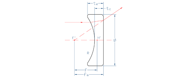
| Specifications | |
| Material | BK7 or UV Fused Silica |
| BK7 or UV Fused Silica | +0.0, -0.1mm |
| Center Thickness Tolerance | +/-0.1mm |
| Paraxial Focal Length | +/-0.5% |
| Clear Aperture | >90% |
| Surface Quality | 40-20 S/D |
| Contration | 1 arc min |
| Coating | Single Layer MgF2 or "V"AR coating |
BK7 Pl-cv Lenses
| Part Number | Φ | R | Tc | Te | EFL |
| PCV-063-R063 | 6.35 | -6.350 | 2.5 | 3.170 | -12.5 |
| PCV-063-R129 | 6.35 | -12.912 | 2.5 | 2.820 | -25 |
| PCV-127-R129 | 12.7 | -12.912 | 2.5 | 3.830 | -25 |
| PCV-127-R258 | 12.7 | -25.859 | 2.5 | 3.140 | -20 |
| PCV-127-R387 | 12.7 | -38.730 | 2.5 | 2.920 | -75 |
| PCV-127-R515 | 12.7 | -51.520 | 2.5 | 2.820 | -100 |
| PCV-254-R129 | 25.4 | -12.912 | 2.5 | 9.400 | -25 |
| PCV-254-R258 | 25.4 | -25.859 | 2.5 | 5.170 | -50 |
| PCV-254-R387 | 25.4 | -38.730 | 2.5 | 4.220 | -75 |
| PCV-254-R515 | 25.4 | -51.520 | 2.5 | 3.780 | -100 |
| PCV-254-R774 | 25.4 | -77.450 | 2.5 | 3.350 | -150 |
| PCV-254-R1035 | 25.4 | -103.510 | 2.5 | 3.130 | -200 |
| PCV-508-R387 | 50.8 | -38.730 | 2.5 | 9.960 | -75 |
| PCV-508-R515 | 50.8 | -51.520 | 2.5 | 7.830 | -100 |
| PCV-508-R774 | 50.8 | -77.450 | 2.5 | 5.950 | -150 |
| PCV-508-R1035 | 50.8 | -103.510 | 2.5 | 5.060 | -200 |
| PCV-508-R1290 | 50.8 | -129.060 | 2.5 | 4.540 | -250 |
| PCV-508-R2594 | 50.8 | -259.400 | 2.5 | 3.510 | -500 |
Like plano-concave lenses, double-concave lenses have negative foccal lengths, diverge collimated incident light and form only virtual image which are seen through the lenses. They are often used to expand light beam or increase focal lengths in existing systems and are normally used in combination with other lenses. In a single lens application you shoud consider using them in prefenrence to a single plano-concave lens if the magnification lies in the region.
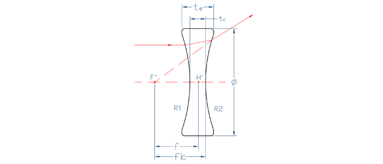
| Specifications | |
| Material | BK7 or UV Fused Silica |
| BK7 or UV Fused Silica | +0.0, -0.1mm |
| Center Thickness Tolerance | +/-0.1mm |
| Paraxial Focal Length | +/-0.5% |
| Clear Aperture | >90% |
| Surface Quality | 40-20 S/D |
| Contration | 1 arc min |
| Coating | Single Layer MgF2 or "V"AR coating |
BK7 Bi-cv Lenses
| Part Number | Φ | R | Tc | Te | EFL |
| DCV-063-R068 | 6.35 | -6.851 | 2.5 | 3.750 | -6.3 |
| DCV-063-R134 | 6.35 | -13.410 | 2.5 | 3.120 | -12.5 |
| DCV-127-R134 | 12.7 | -13.410 | 2.5 | 5.070 | -12.5 |
| DCV-127-R1263 | 12.7 | -26.300 | 2.5 | 3.760 | -25 |
| DCV-127-R521 | 12.7 | -52.120 | 2.5 | 3.130 | -50 |
| DCV-127-R779 | 12.7 | -77.980 | 2.5 | 2.920 | -75 |
| DCV-127-R1035 | 12.7 | -103.510 | 2.5 | 2.820 | -100 |
| DCV-254-R263 | 25.4 | -26.300 | 2.5 | 7.740 | -25 |
| DCV-254-R521 | 25.4 | -52.120 | 2.5 | 5.040 | -50 |
| DCV-254-R779 | 25.4 | -77.980 | 2.5 | 4.190 | -75 |
| DCV-254-R1035 | 25.4 | -103.510 | 2.5 | 3.760 | -100 |
| DCV-254-R1554 | 25.4 | -155.466 | 2.5 | 3.340 | -150 |
| DCV-254-R2071 | 25.4 | -207.148 | 2.5 | 3.130 | -200 |
| DCV-508-R779 | 50.8 | -77.980 | 2.5 | 9.360 | -75 |
| DCV-508-R1035 | 50.8 | -103.510 | 2.5 | 7.600 | -100 |
| DCV-508-R1554 | 50.8 | -155.466 | 2.5 | 5.880 | -150 |
| DCV-508-R2071 | 50.8 | -207.148 | 2.5 | 5.030 | -200 |
| DCV-508-R2588 | 50.8 | -258.824 | 2.5 | 4.520 | -250 |
| DCV-508-R5176 | 50.8 | -517.600 | 2.5 | 3.510 | -500 |
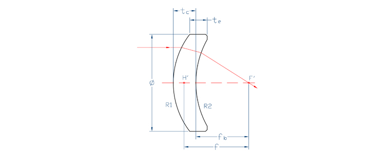
These lenses may be used to increase the numerical aperture of a positive lens assembly, without an undue increase in the aberrations.
| Specifications | |
| Material | BK7 or UV Fused Silica |
| BK7 or UV Fused Silica | +0.0, -0.1mm |
| Center Thickness Tolerance | +/-0.1mm |
| Paraxial Focal Length | +/-0.5% |
| Clear Aperture | >90% |
| Surface Quality | 40-20 S/D |
| Contration | 1 arc min |
| Coating | Single Layer MgF2 or "V"AR coating |
Positive Meniscus Lenses
| Part Number | Φ | R1 | Tc | Te | EFL |
| MNP-254-R515R1000 | 25.4 | 51.520 | 4.28 | 3.5 | 200 |
| MNP-254-R851-R2500 | 25.4 | 85.113 | 4.12 | 3.5 | 250 |
| MNP-254-R1025-R3000 | 25.4 | 102.570 | 4.02 | 3.5 | 300 |
| MNP-254-R1267-R3220 | 25.4 | 126.770 | 3.89 | 3.5 | 400 |
| MNP-254-R1554-R3876 | 25.4 | 155.466 | 3.81 | 3.5 | 500 |
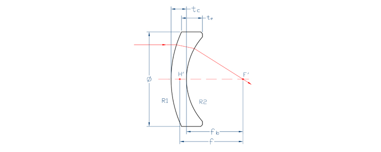
The best lens from where one conjugates is relatively for from the lens or where both conjugates are the same size of the lens.
| Specifications | |
| Material | BK7 or UV Fused Silica |
| BK7 or UV Fused Silica | +0.0, -0.1mm |
| Center Thickness Tolerance | +/-0.1mm |
| Paraxial Focal Length | +/-0.5% |
| Clear Aperture | >90% |
| Surface Quality | 40-20 S/D |
| Contration | 1 arc min |
| Coating | Single Layer MgF2 or "V"AR coating |
Negative Meniscus Lenses
| Part Number | Φ | R1 | Tc | Te | EFL |
| MNN-254-R900-R338 | 25.4 | 90 | 2.32 | 3.92 | -100 |
| MNN-254-R900-R389 | 25.4 | 90 | 2.02 | 3.3 | -125 |
| MNN-254-R1000-R430 | 25.4 | 100 | 3.73 | 4.77 | -150 |
| MNN-254-R950-R457 | 25.4 | 95.0 | 2.86 | 3.8 | -175 |
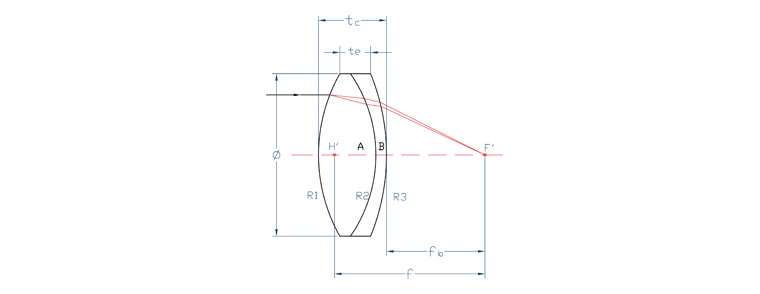
Doublet lens is a closely spaced and often cemented, combination of positive and negative elements of differing refractive index. These elements are chosen so that the chromate aberration is cancelled at two distant and well-separated wavelengths.
| Specifications | |
| Material | According to your design |
| Diameter Tolerance | +0.0, -0.1mm |
| Center Thickness Tolerance | +/-0.1mm |
| Paraxial Focal Length | +/-0.5% |
| Clear Aperture | >90% |
| Surface Quality | 40-20 S/D |
| Surface Figure | λ/8@632.8nm |
| Contration | 3 arc min |
| Coating | Single Layer MgF2 or BBAR coating |
These lenses are used in application requiring magnification only, such as in transforming a point image into a line image or changing the height of an image without changing its width or vice versa. Therefore serving a variety application, such as slit line detector array illumination, bar code scanning, holography, optical information processing and computer, laser projection.

| Specifications | |
| Material | BK7 or UV Fused Silica |
| Dimension Tolerance | +0.0, -0.1mm |
| Center Thickness Tolerance | +/-0.1mm |
| Paraxial Focal Length | +/-1% |
| Clear Aperture | >90% |
| Surface Quality | 40-20 S/D |
| Surface Figure | λ/8@632.8nm |
| Contration | 3 arc min |
| Coating | Upon Request |
Pl-cx Cylindrical Lenses
| Part Number | X | R | Tc | Te | EFL |
| CPCX-254-127-R065 | 25.4 | 6.57 | 7.9 | 3 | 12.7 |
| CPCX-508-254-R197 | 50.8 | 19.7 | 7.64 | 3 | 38.1 |
| CPCX-508-254-R259 | 50.8 | 25.95 | 6.32 | 3 | 50.2 |
| CPCX-508-254-R325 | 50.8 | 32.52 | 5.58 | 3 | 62.9 |
| CPCX-508-254-R390 | 50.8 | 39.09 | 5.12 | 3 | 75.6 |
| CPCX-508-508-R517 | 50.8 | 51.7 | 9.67 | 3 | 100 |
| CPCX-508-508-R775 | 50.8 | 77.55 | 7.28 | 3 | 150 |
| CPCX-508-508-R1034 | 50.8 | 103.4 | 6.17 | 3 | 200 |
| CPCX-508-508-R1551 | 50.8 | 155.1 | 5.09 | 3 | 300 |
| CPCX-508-254-R239 | 50.8 | 23.09 | 6.81 | 3 | 50.2 |
| CPCX-508-254-R460 | 50.8 | 46 | 4.79 | 3 | 100 |
| CPCX-508-508-R690 | 50.8 | 69 | 7.85 | 3 | 150 |
| CPCX-508-508-R920 | 50.8 | 92 | 6.58 | 3 | 200 |
| CPCX-508-508-R1380 | 50.8 | 138 | 5.36 | 3 | 300 |

| Specifications | |
| Material | BK7 or UV Fused Silica |
| Dimension Tolerance | +0.0, -0.1mm |
| Center Thickness Tolerance | +/-0.1mm |
| Paraxial Focal Length | +/-1% |
| Clear Aperture | >90% |
| Surface Quality | 40-20 S/D |
| Surface Figure | λ/8@632.8nm |
| Contration | 3 arc min |
| Coating | Upon Request |
Pl-cv Cylindrical Lenses
| Part Number | X | R | Tc | Te | EFL |
| CPCV-254-127-R033 | 25.4 | -3.31 | 6 | 7.36 | -6.4 |
| CPCV-254-127-R065 | 25.4 | -6.57 | 6 | 9.58 | -12.7 |
| CPCV-254-127-R129 | 25.4 | -12.92 | 6 | 7.4 | -25 |
| CPCV-508-190-R258 | 50.8 | -25.85 | 6 | 7.62 | -50 |
| CPCV-508-254-R750 | 50.8 | -38.77 | 6 | 7.97 | -75 |
| CPCV-508-254-R517 | 50.8 | -51.7 | 6 | 7.46 | -100 |
| CPCV-508-254-R775 | 50.8 | -77.55 | 6 | 6.97 | -150 |
| CPCV-508-254-R1034 | 50.8 | -103.4 | 6 | 6.72 | -200 |
| CPCV-508-190-R116 | 50.8 | -11.68 | 2.5 | 6.73 | -25.4 |
| CPCV-508-254-R230 | 50.8 | -23.09 | 2.5 | 5.99 | -50.2 |
| CPCV-508-254-R460 | 50.8 | -46 | 2.5 | 4.15 | -100 |
| CPCV-508-508-R690 | 50.8 | -69 | 2.5 | 7.15 | -150 |
| CPCV-508-508-R920 | 50.8 | -92 | 2.5 | 5.93 | -200 |
| CPCV-508-508-R1380 | 50.8 | -138 | 2.5 | 4.76 | -300 |
Penta prism have two important properties. The first is that as the image is deviated by 90 degrees it is neither inverted nor reversed. The second is that the penta-prism is a constant deviation prism, meaning that the same exact 90-degree deviation angle applies to all rays transmitted by the useful aperture regardless of the angles between these rays and the optical axis. The deviation is thus independent of the prism orientation, making the penta-prism especially important in application in which prism orientation can’t be precisely controlled. This prism is commonly used in optical tooling, alignment, range finding, surveying, and other instrumental applications.

| Specifications | |
| Material | BK7 |
| Dimension Tolerance | +0.0, -0.1mm |
| Clear Aperture | >90% |
| Deviation | 10 arc sec |
| Surface Quality | 40-20 S/D |
| Flatness | λ/8@632.8nm |
Coating | AR coating at input&output face HR coating at reflective faces |
BK7 Penta Prisms
| Part Number | Size A(mm) | Size H(mm) |
| PTP-070-070 | 7.0 | 7.0 |
| PTP-100-100 | 10.0 | 10.0 |
| PTP-127-127 | 12.7 | 12.7 |
| PTP-150-150 | 15.0 | 15.0 |
| PTP-200-200 | 20.0 | 20.0 |
| PTP-254-254 | 25.4 | 25.4 |
Dove prisms are used as image rotators in variety of optic-mechanical system. As the prism is rotated, the image passing through will rotate at twice the angular rate of the prism. Light entering the dove prism must be parallel or collimated, because the length of the prism is four or five times the height of the prism. The hypotenuse face of a dove prism is the face of the largest area. Normally the dove prism is used in the total internal reflection mode, with the hypotenuse face un-aluminized. Cleanliness of this face is important.

| Specifications | |
| Material | BK7 |
| Dimension Tolerance | +0.0, -0.1mm |
| Clear Aperture | >90% |
| Angle Tolerance | 1 arc min |
| Surface Quality | 40-20 S/D |
| Flatness | λ/8@632.8nm |
Coating | Upon Request |
BK7 Penta Prisms
| Part Number | Size H(mm) | Size A(mm) | Size B(mm) |
| DPR-100-100-BK7 | 10 | 42.3 | 10 |
| DPR-150-150-BK7 | 15 | 63.5 | 15 |
| DPR-200-200-BK7 | 20 | 84.7 | 20 |
| DPR-100-100-UVFS | 10 | 44.9 | 10 |
| DPR-150-150-UVFS | 15 | 67.4 | 15 |
| DPR-200-200-UVFS | 20 | 89.9 | 20 |
Right-angle prisms are often preferable to an inclined mirror in applications involving severe acoustic or inertial loads. This is because a right-angle prism is easier to mount and deforms much less than a mirror in response to external mechanical stress. Very high transmission can be achieved by using the hypotenuse face in total internal reflection, and by antireflective coating on the entrance and exit faces. Alternatively, the hypotenuse face can be used in external reflection, and coating with a metallic reflective coating.

| Specifications | |
| Material | BK7, UV Fused Silica |
| Dimension Tolerance | +0.0, -0.1mm |
| Clear Aperture | >90% |
| Angle Tolerance | 1 arc min |
| Surface Quality | 40-20 S/D |
| Flatness | λ/8@632.8nm |
Coating | Upon Request |
Right Angle Prisms
| Part Number | A=B(mm) | Part Number | A=B(mm) |
| RAP-127-BK7 | 12.7 | RAP-127-UVFS | 12.7 |
| RAP-150-BK7 | 15.0 | RAP-150-UVFS | 15.0 |
| RAP-200-BK7 | 20.0 | RAP-200-UVFS | 20.0 |
| RAP-254-BK7 | 25.4 | RAP-254-UVFS | 25.4 |
It has three mutually perpendicular surfaces and a hypotenuse face, light entering through the hypotenuse is reflected by each of the three surfaces in turn and will emerge though the hypotenuse face parallel to the entering beam regardless of the orientation the incident beam, it is often used to the distance measurement, optical signal process and laser interferometer.

| Specifications | |
| Material | BK7 |
| Dimension Tolerance | +0.0, -0.1mm |
| Clear Aperture | >90% |
| Deviation | 10 arc sec |
| Surface Quality | 40-20 S/D |
| Flatness | λ/8@632.8nm |
| Wavefront Distortion | λ/4@632.8nm |
| Coating | Upon Request |
BK7 Retro-Reflectors
| Part Number | Diameter Φ(mm) | Height H(mm) |
| RRP-127-095 | 12.7 | 9.5 |
| RRP-254-188 | 25.4 | 18.8 |
| RRP-380-285 | 38 | 28.5 |
| RRP-640-480 | 64 | 48.0 |
Roof prism is combined with a right angle prism and a totally internally reflecting roof and they are attached by them largest aquare surfaces. It can invert and reverse an image, also, deflect the image 90°. Therefore, it is often used in Terrestrial telescopes, Viewing systems and Rangefinders.

| Specifications | |
| Material | BK7 |
| Dimension Tolerance | +0.0, -0.1mm |
| Clear Aperture | >90% |
| Deviation | 10 arc sec |
| Surface Quality | 60-40 S/D |
| Flatness | λ/8@632.8nm |
Coating | Upon Request |
Roof Prisms
| Part Number | A=B(mm) | H(mm) |
| RFP-230-315 | 23 | 31.5 |
These two prisms can expand or contract the beam in one direction without any changes in the other direction. By adjusting the angles among the incident beam and two prisms, the shape of the beam can be changed. It is very easy to turn elliptical beam into circular beam.

| Specifications | |
| Material | N-SF11 |
| Dimension Tolerance | +0.0, -0.1mm |
| Clear Aperture | >90% |
| Angle Tolerance | 29°27'±20'' |
| Surface Quality | 40-20 S/D |
| Flatness | λ/8@632.8nm |
Coating | MgF2 |
Anamorphic Prisms
| Part Number | A | B | C |
| ANP-120-085-SF11 | 12 | 12 | 8.5 |
Other prisms are available upon request
Plate beamsplitter consists of thin window. When using it, the two partial beams travel different optical paths. And the optical paths are decided on the thickness of plates and the incident angle.

| Specifications | |
| Material | BK7 or others |
| Dimension Tolerance | +0.0, -0.1mm |
| Thinckness Tolerance | +/-0.1mm |
| Clear Aperture | >90% |
| Parallelism | 30 arc sec |
| Surface Quality | 40-20 S/D |
| Flatness | λ/8@632.8nm |
| Coating | T/R=50/50±5% or others |
Cube beamsplitters are constructed by cementing two right angle prisms together with the appropriate interference coating on hypotenuse. The absorption loss to the coating is minimal. Transmission and reflection approach 50% (average) though the output is partially polarized.

| Specifications | |
| Material | BK7 |
| Dimension Tolerance | +0.0, -0.1mm |
| Clear Aperture | >90% |
| Deviation | 1 arc min |
| Surface Quality | 40-20 S/D |
| Flatness | λ/8@632.8nm |
| Coating | T/R=50/50±5% or others |
Polarizing cube beamsplitters split randomly polarized beams into two orthogonal, linearly polarized components: S-polarized light is reflected at a 90 deg angle while P-polarized light is transmitted. Each beamsplitter consists of a pair of precision high tolerance right angle prisms cemented together with a dielectric coating on the hypotenuse of one of the prisms. A multi-layer antireflective coating has been applied to each face of the beamsplitter in order to produce maximum transmission efficiency.

| Specifications | |
| Material | BK7 |
| Dimension Tolerance | +0.0, -0.1mm |
| Clear Aperture | >90% |
| Deviation | 1 arc min |
| Surface Quality | 40-20 S/D |
| Flatness | λ/8@632.8nm |
| Coating | Tp>98% & Ts<1% Extinction ratio>150:1 |
By adding a wedge and with partial reflective coating on one of the leaning surfaces of penta prisms, it can be used as a beamsplitter. It is often used in plumb level, surveying, alignment, rangefinding and optical tooling.

| Specifications | |
| Material | BK7 |
| Dimension Tolerance | +0.0, -0.1mm |
| Clear Aperture | >90% |
| 90°Deviation | 5 arc sec |
| 180°Deviation | 10 arc sec |
| Surface Quality | 40-20 S/D |
| Flatness | λ/8@632.8nm |
| Coating | T/R=50/50±5% or others |

| Specifications | |
| Material | BK7, UVFS or others |
| Dimension Tolerance | +0.0, -0.1mm |
| Thinckness Tolerance | +/-0.1mm |
| Clear Aperture | >90% |
| Surface Quality | 40-20 S/D |
| Wavefront Distortion | λ/8@632.8nm |
| Parallelism | 10 arc sec |
| Coating | "V"AR coating, BBAR coating or others |
Parallel Windows
| Part Number | Ø(mm) | T(mm) |
| WIN-127-031-BK7 | 12.7 | 3.175 |
| WIN-127-060-BK7 | 12.7 | 6 |
| WIN-254-060-BK7 | 25.4 | 6 |
| WIN-254-063-BK7 | 25.4 | 6.35 |
| WIN-508-100-BK7 | 50.8 | 10 |
| WIN-127-031-UVFS | 12.7 | 3.175 |
| WIN-127-060-UVFS | 12.7 | 6 |
| WIN-254-060-UVFS | 25.4 | 6 |
| WIN-254-063-UVFS | 25.4 | 6.35 |

| Specifications | |
| Material | BK7, UVFS or others |
| Dimension Tolerance | +0.0, -0.1mm |
| Thinckness Tolerance | +/-0.1mm |
| Clear Aperture | >90% |
| Surface Quality | 40-20 S/D |
| Wavefront Distortion | λ/8@632.8nm |
| Parallelism | 10 arc sec |
| Coating | "V"AR coating, BBAR coating or others |
BK7 Rectangular Windows
| Part Number | A(mm) | B(mm) | T(mm) |
| WIN-127-063-030 | 6.35 | 12.7 | 3.0 |
| WIN-254-127-063 | 12.7 | 25.4 | 6.35 |

| Specifications | |
| Material | BK7, UVFS or others |
| Dimension Tolerance | +0.0, -0.1mm |
| Thinckness Tolerance | +/-0.1mm |
| Clear Aperture | >90% |
| Surface Quality | 40-20 S/D |
| Wavefront Distortion | λ/8@632.8nm |
| Parallelism | 10 arc sec |
| Coating | "V"AR coating, BBAR coating or others |
BK7 Square Windows
| Part Number | A(mm) | T(mm) |
| WIN-127-030 | 12.7 | 3.0 |
| WIN-254-063 | 25.4 | 6.35 |

| Specifications | |
| Material | BK7, UV Fused Silica |
| Dimension Tolerance | +0.0, -0.1mm |
| Thinckness Tolerance | +/-0.1mm |
| Clear Aperture | >90% |
Brewster Angle | 56.6° for BK7 at 588nm 56.1° for UV Fused Silica at 308nm |
| Surface Quality | 40-20 S/D |
| Wavefront Distortion | λ/8@632.8nm |
| Parallelism | 10 arc sec |
Brewster Windows
| Part Number | Ø(mm) | T(mm) |
| WINB-080-020-BK7 | 8.0 | 2.0 |
| WINB-100-020-BK7 | 10.0 | 2.0 |
| WINB-160-020-BK7 | 16.0 | 2.0 |
| WINB-254-020-BK7 | 25.4 | 2.0 |
| WINB-060-020-UVFS | 6.0 | 2.0 |
| WINB-080-020-UVFS | 8.0 | 2.0 |
| WINB-100-020-UVFS | 10.0 | 2.0 |
| WINB-160-030-UVFS | 16.0 | 3.0 |
| WINB-254-030-UVFS | 25.4 | 3.0 |
Compare to metallic mirrors, dielectric mirrors exhibit high reflection, high damage threshold and good adhesion, but the bandwidth is not so wide as metallic mirrors.

| Specifications | |
| Material | BK7 or others |
| Dimension Tolerance | +0.0, -0.1mm |
| Thinckness Tolerance | +/-0.1mm |
| Clear Aperture | >90% |
| Surface Quality | 40-20 S/D |
| Flatness | λ/8@632.8nm |
| Coating | R>99.8% R=(Rs+Rp)/2 |
Metallic mirrors are excellent broad band reflectors. Toptec provides protected Aluminium, silver mirrors and enhanced Al mirrors as well.

| Specifications | |
| Material | BK7 or others |
| Dimension Tolerance | +0.0, -0.1mm |
| Thinckness Tolerance | +/-0.1mm |
| Clear Aperture | >90% |
| Surface Quality | 40-20 S/D |
| Flatness | λ/8@632.8nm |
| Coating | Al, Au, Ag protected |
Low-order Waveplates which can be replaced by multi-order waveplate is designed to give a retardance of several full waves plus the desired fraction. This result a single, physically robust component with desired performance. However, even small variation in wavelength or temperature will result in signification changes in the desired fractional retardance.

| Specifications | |
| Material | Crystal Quartz, MgF2 |
| Dimension Tolerance | +0.0, -0.1mm |
| Wavefront Distortion | λ/10@632.8nm |
| Retardation Tolerance | λ/500@632.8nm |
| Wavelength Range | 240-2100nm |
| Surface Quality | 20-10 S/D |
| Parallelism | 3 arc sec |
| Coating | R<0.15% at Center Wavelength |
Standard Products
| Half Waveplate | Quarter Waveplate |
| WPL-100-1/2-λ | WPL-100-1/4-λ |
| WPL-127-1/2-λ | WPL-127-1/4-λ |
| WPL-150-1/2-λ | WPL-150-1/4-λ |
| WPL-200-1/2-λ | WPL-200-1/4-λ |
| WPL-254-1/2-λ | WPL-254-1/4-λ |
| Standard Wavelength:266nm,355nm,532nm,632.8nm,780nm,808nm,850nm,980nm,1064nm,1310nm,1480nm,1550nm | |
It is constructed of two multi-order waveplates with axis crossed. Thus, it performs as a zero-order waveplatebecause of the effect of two plates counteracting each other. It has wide temperature bandwidth and wavelength bandwidth properties.Because it is cemented, the damage threshold must be considered (about 10MW/cm2) when used.

| Specifications | |
| Material | Crystal Quartz |
| Dimension Tolerance | +0.0, -0.1mm |
| Wavefront Distortion | λ/10@632.8nm |
| Retardation Tolerance | λ/300@632.9nm |
| Wavelength Range | 240-2100nm |
| Surface Quality | 20-10 S/D |
| Parallelism | 3 arc sec |
| Coating | R<0.15% at Center Wavelength |
Standard Products
| Half Waveplate | Quarter Waveplate |
| WPZO-100-1/2-λ | WPZO-100-1/4-λ |
| WPZO-127-1/2-λ | WPZO-127-1/4-λ |
| WPZO-150-1/2-λ | WPZO-150-1/4-λ |
| WPZO-200-1/2-λ | WPZO-200-1/4-λ |
| WPZO-254-1/2-λ | WPZO-254-1/4-λ |
Its performance is as good as cemented zero-order waveplate. Additionally, the air-spaced construction enable it suit for the high power laser application. The damage threshold is more than 500MW/cm2.

| Specifications | |
| Material | Crystal Quartz |
| Dimension Tolerance | +0.0, -0.1mm |
| Wavefront Distortion | λ/10@632.8nm |
| Retardation Tolerance | λ/300@632.9nm |
| Wavelength Range | 240-2100nm |
| Surface Quality | 20-10 S/D |
| Parallelism | 3 arc sec |
| Coating | R<0.15% at Center Wavelength |
Standard Products
| Half Waveplate | Quarter Waveplate |
| WPZA-100-1/2-λ | WPZA-100-1/4-λ |
| WPZA-127-1/2-λ | WPZA-127-1/4-λ |
| WPZA-150-1/2-λ | WPZA-150-1/4-λ |
| WPZA-200-1/2-λ | WPZA-200-1/4-λ |
| WPZA-254-1/2-λ | WPZA-254-1/4-λ |
This type of zero order waveplates is constructed of two multiple order wavewplate with their axes crossed. Thus, the effect of the first plate is canceled by the second, except for the residual difference between them.

| Specifications | |
| Material | Crystal Quartz |
| Dimension Tolerance | +0.0, -0.1mm |
| Wavefront Distortion | λ/10@632.8nm |
| Retardation Tolerance | λ/300@632.9nm |
| Wavelength Range | 240-2100nm |
| Surface Quality | 20-10 S/D |
| Parallelism | 3 arc sec |
| Coating | R<0.15% at Center Wavelength |
| Half Waveplate | Quarter Waveplate |
| WPZC-100-1/2-λ | WPZC-100-1/4-λ |
| WPZC-127-1/2-λ | WPZC-127-1/4-λ |
| WPZC-150-1/2-λ | WPZC-150-1/4-λ |
| WPZC-200-1/2-λ | WPZC-200-1/4-λ |
| WPZC-254-1/2-λ | WPZC-254-1/4-λ |
| Standard Wavelength:266nm,355nm,532nm,632.8nm,780nm,808nm,850nm,980nm,1064nm,1310nm,1480nm,1550nm | |
The true zero-order waveplate means that thickness of waveplate is very thin (less than 0.1mm) which make the true-zero-order waveplate ecellent in temperature, wavelength and incident angle (about 20º) bandwidth.Therefore, it is excellent choice for the highly accurate application. It is cemented with a block of glass which is limited to low and medium power application.

| Specifications | |
| Material | Crystal Quartz |
| Dimension Tolerance | +0.0, -0.1mm |
| Wavefront Distortion | λ/10@632.8nm |
| Retardation Tolerance | λ/500@632.9nm |
| Wavelength Range | 240-2100nm |
| Surface Quality | 20-10 S/D |
| Parallelism | 3 arc sec |
| Coating | R<0.15% at Center Wavelength |
Standard Products
| Half Waveplate | Quarter Waveplate |
| WPCT-100-1/2-λ | WPCT-100-1/4-λ |
| WPCT-127-1/2-λ | WPCT-127-1/4-λ |
| WPCT-150-1/2-λ | WPCT-150-1/4-λ |
| WPCT-200-1/2-λ | WPCT-200-1/4-λ |
| WPCT-254-1/2-λ | WPCT-254-1/4-λ |
| Standard Wavelength: 532nm,632.8nm,780nm,808nm,850nm,980nm,1064nm,1310nm,1480nm,1550nm | |
In order to enable the waveplate suit for high damage threshold (more than 1GW/cm2) application, Toptec provides a single plate of true zero-order waveplate.The thickness of this waveplate means handling can be difficult, we can provide mounts upon request.

| Specifications | |
| Material | Crystal Quartz |
| Dimension Tolerance | +0.0, -0.1mm |
| Wavefront Distortion | λ/10@632.8nm |
| Retardation Tolerance | λ/500@632.9nm |
| Wavelength Range | 240-2100nm |
| Surface Quality | 20-10 S/D |
| Parallelism | 3 arc sec |
| Coating | R<0.15% at Center Wavelength |
Standard Products
| True Zero-order Waveplates | |
| Half Waveplate | Quarter Waveplate |
| WPT-100-1/2-λ | WPT-100-1/4-λ |
| WPT-127-1/2-λ | WPT-127-1/4-λ |
| WPT-150-1/2-λ | WPT-150-1/4-λ |
| WPT-200-1/2-λ | WPT-200-1/4-λ |
| WPT-254-1/2-λ | WPT-254-1/4-λ |
| Standard Wavelength λ/4: 1310nm,1480nm,1550nm | |
| Standard Wavelength λ/2: 980nm,1064nm,1310nm,1480nm,1550nm | |
In order to enable the waveplate suit for high damage threshold (more than 1GW/cm2) application, Toptec provides a single plate of true zero-order waveplate.The thickness of this waveplate means handling can be difficult, we can provide mounts upon request.

| Specifications | |
| Material | Crystal Quartz |
| Dimension Tolerance | +0.0, -0.1mm |
| Wavefront Distortion | λ/10@632.8nm |
| Retardation Tolerance | λ/100@700-1000nm |
| Wavelength Range | 240-2100nm |
| Surface Quality | 20-10 S/D |
| Parallelism | 3 arc sec |
| Coating | R<0.15% at Center Wavelength |
Standard Products
| Half Achronatic Waveplate | Quarter Achromatic Waveplate |
| WPAO-127-1/2-λ | WPAO-127-1/4-λ |
| WPAO-150-1/2-λ | WPAO-150-1/4-λ |
| WPAO-200-1/2-λ | WPAO-200-1/4-λ |
| WPAO-254-1/2-λ | WPAO-254-1/4-λ |
Dual Wavelength Waveplate is THG-PR polarization ratator and used to manage the polarizaton of laser beam maximum conversion efficiency of third harmaonic generation(THG),In fact, it is a low order or multi-order waveplate,but which are suitable for two different wavelengths with different retardations. The dual wavelength waveplate is often applied in laser harmornic generation.

| Specifications | |
| Material | Crystal Quartz |
| Dimension Tolerance | +0.0, -0.1mm |
| Wavefront Distortion | λ/10@632.8nm |
| Retardation Tolerance | λ/500@632.8nm |
| Wavelength Range | 240-2100nm |
| Surface Quality | 20-10 S/D |
| Parallelism | 3 arc sec |
Coating | R<0.2% at fundermental Wavelength and R<0.5% at SHG Wavelength |
MgF2 is a birefrigent material crystal with excellent physical and chemical properties. It provides wide transparent range, high transmissibility. MgF2 is a rugged material resistant to chemical etching, mechanical, and thermal shock. High vacuum UV transmission and resistance to laser damage make MgF2 a popular choice for VUV and excimer laser windows, polarizers, and lenses.
Main Properties of MgF2
| Lattice constant | a=4.621A; c=3.053A |
| Melting Point | 1255℃ |
| Density | 3.17g/cm3 (at 291K) |
| Mohs hardness | 6 |
| Thermal conductivity | 0.3 Wm-1K-1 |
| Expansion coefficient | aa=13.7x10⁻⁶/K; ac=8.48x10⁻⁶/K |
| Elastic Coefficients | C11=140.2 C12=89.5 C44=56.8 |
| Transparence range | 0.11-7.5µm |
| Refraction Index | @405nm no=1.3836, ne=1.3957 |
Specification of MgF2 Window
| Diameter Tolerance | +0.0/-0.1mm |
| Thickness Tolerance | +/-0.1mm |
| Flatness | λ/4 at 632.8nm |
| Surface Quality | 40-20 |
| Parallelism | <3 arc min |
| Clear Aperture | >90% |
Calcium Fluoride (CaF2) is a crystal which has good transmission from 170nm to 7800nm. It is slightly soluble in water and is susceptible to thermal shock. Common uses of CaF2 include IR components such as windows, lenses and Prisms.
Main Properties of CaF2
| Melting Point | 1360℃ |
| Density | 3.18g/cm3 (at 291K) |
| Mohs hardness | 4 |
| Thermal conductivity | 9.71 Wm-1K-1 |
| Expansion coefficient | 18.85x10⁻⁶/K |
| Elastic Coefficients | C11=164 C12=53 C44=33.7 |
| Transparence range | 0.13-10µm |
| Refraction Index | n=1.6921-1.3161 |
Specification of CaF2 Window
| Diameter Tolerance | +0.0/-0.1mm |
| Thickness Tolerance | +/-0.1mm |
| Flatness | λ/4 at 632.8nm |
| Surface Quality | 40-20 |
| Parallelism | <3 arc min |
| Clear Aperture | >90% |
Silicon (Si) is commonly used as a substrate material for infrared reflectors and windows in the 1.5μ m-8μm region. The strong absorption band at 9μm makes it unsuitable for CO2 laser transmission applications but it is frequently used for laser mirrors because of its high thermal conductivity and low density. Silicon is also a useful transmitter in 20μm range.
Silicon is the most abundant electropositive element in the Earth’s crust. It’s a metalloid with a marked metallic luster and very brittle. It is usually tetravalent in its compounds, although sometimes they are bivalent and purely electropositive in its chemical behavior. Moreover, pentacoordinated and hexacoordinated silicon compounds are also known.
Silicon lenses are popular for many applications in the IR. They are typically used for imaging applications in the 3-5μm region of the spectrum, making them excellent for security and military applications. They can also be used to collimate infrared lasers. These lenses are coated with a BBAR coating that provides 98% transmission in the 3-5μm spectral range.
Main Properties of Si
| Material Type | CZ FZ,N or P |
| Crystal Direction | [100],[111] |
| Resistivity | 0.003-50 Ohm/cm |
| Melting Point | 1410℃ |
| Density | 2.33g/cm3 |
| Knoop Hardness | 1150kg/mm2 |
| Thermal Conductivity | 163.3 J/k.m.s@273K |
| Transmittance Range | 1um-10um,30um-300um |
| Refraction Index | 3.4179@10µm |
Specification of Si Window & Mirror
| Diameter Tolerance | +0.0/-0.1mm |
| Thickness Tolerance | +/-0.1mm |
| Flatness | λ/8 at 632.8nm |
| Surface Quality | 40-20 |
| Parallelism | <3 arc min |
| Clear Aperture | >90% |
| Coating | AR or HR coating |
Germanium (Ge) is used widely for lenses and windows in thermal imaging and FLIR applications. Its high index of refraction makes it of particular interest. Useful transmission range of Germanium windows is from 2 to 12μm.Germanium is opaque in the visible.
Germanium has the property of thermal runaway, meaning that the transmission decreases as temperature increases. As such, Ge window should be used at temperatures below 100°C. The higher Knoop Hardness of Germanium (780) makes it ideal for IR applications requiring rugged optics. Germanium’s high density (5.33/cm 3) should be considered when designing for weight-sensitive systems.
Main Properties of Ge
| Material Type | N or P |
| Resistivity | 4-50 Ohm/cm |
| Density | 5.33g/cm3 |
| Knoop Hardness | 780kg/mm2 |
| Thermal Expansion Coefficient | 5.5x10⁻⁶/K |
| Transmittance Range | 2µm-4µm |
| Refraction Index | 4.003@10µm |
Specification of Ge Lens
| Diameter Tolerance | +0.0/-0.1mm |
| Thickness Tolerance | +/-0.1mm |
| Flatness | λ/4 at 632.8nm |
| Surface Quality | 40-20 |
| Parallelism | <3 arc min |
| Clear Aperture | >90% |
| Coating | AR or BBAR coating |
ZnSe is used for optical windows, lenses, mirrors, prisms and optical blanks, plates, disks, sheets, slabs particularly for infrared applications Zinc Selenide (ZnSe) — transparent in wide spectral range from yellow (visible) to far IR. ZnSe material is a chemically inert, non-hygroscopic and highly pure product that is very effective in many optical applications due to its extremely low bulk losses, high resistance to thermal shock and stability in virtually all environments, easily machined. To obtain superior transmittance, ZnSe crystals are grown by Chemical Vapor Deposition process (CVD). Zinc Selenide CVD is polycrystalline material, demonstrates superior CO2 laser transmittance and is employed in the transmission optical components used in CO2 laser processing. ZnSe (Zinc Selenide) Chemical Vapor Deposition (CVD) material is produced by synthesis from zinc vapour and H2Se gas, forming as sheets on graphite susceptors (ZnSe-CVD processes). Chemical purity of CVD-ZnSe 99.999%. It has à polycrystalline structure; the grain size of Zinc Selenide CVD material is controlled to produce maximum strength. The transmission range of Zinc Selenide ZnSe-CVD is (0.5 – 20) microns. ZnSe CVD used for high power CO2 laser optics at 10.6 microns, for protective optics windows or optical elements in FLIR (forward looking infrared) thermal imaging equipment, optics for medical and industrial applications (optical plane parallel windows (plates, disks, sheets, slabs, blanks), wedged windows, Brewster windows, optical meniscus, spherical and cylindrical lenses, prisms, resonator mirrors of CO2 laser). Single crystal ZnSe Zinc Selenide is available, but is not common, it has lower bulk losses and thus more effective for CO2 optics.
Main Properties of ZnSe(CVD)
| Density | 5.27 g/cm3 |
| Melting Point | 1525℃ |
| Thermal Conductivity | 18 W/(m K)@298K |
| Thermal Expansion | 7.1 x 10⁻⁶/℃ at 273K |
| Hardness | 339 J/(kg K) |
| Transmission Range | 0.6-21.0µm |
| Refractive Index | 2.4028@10µm |
Specification of ZnSe Lens
| Design Wavelength | 10.6µm |
| Focal Length Tolerance | +/-1% |
| Diameter Tolerance | +0.0/-0.1mm |
| Thickness Tolerance | +/-0.1mm |
| Flatness | λ/4 at 632.8nm |
| Surface Quality | 40-20 |
| Centration | <3 arc min |
| Clear Aperture | >90% |
| Coating | AR@10.6µm or BBAR@8-14µm |
KTP crystal is the most commonly used for SHG (Frequency doubling) of Nd-doped laser for green/red output. It is widely used in both commercial and military lasers including laboratory and medical systems, rang-finders, lidar, optical communication and industrial systems.
Advantages
Large nonlinear optical coefficient
High electro-optic coefficient and low dielectric constant
High thermal conductivity
Moisture free,chemically and mechanically stable
Large figure of merit
Chemical and Structural Properties
| Orthorhombic, Space group Pna21, Point group mm2 |
| a=6.404Å, b=10.616Å, c=12.814Å, Z=8 |
| 1172ºC incongruent |
| ~5 |
| 3.01g/cm3 |
| 0.13W/cm/K |
| αx=11x10-6/K, αy=9x10⁻⁶/K, αz=0.6x10⁻⁶/K |
Optical and nonlinear optical properties
| Transparency Range | 350-4500nm |
| SHG Phase Matchabel Range | 497~1800nm (TypeII) |
| Therm-optic Coefficients(/ºC) | dnx/dT=-1.1x10-5,dny/dT=-1.3x10-5,dnz/dT=1.6x10-5 |
| Absorption Coefficients | <0.1%/cm at 1064nm, <1%/cm at 532nm |
For Type II SHG of a Nd:YAG Laser at 1064nm | Temperature Acceptance:24ºC-cm Spectral Acceptance:0.56nm-cm Angular Acceptance:14.2mrad-cm(φ);55.3mrad-cm(θ) Walk-off Angle:0.55° |
| NLO Coefficients | deff(II)≈(d24-d15)sin2 φsin2θ-(d15sin2φ+d24cos2 φ)sinθ |
Non-vanished NLO Susceptibilities | d31=6.5pm/V, d24=-7.6pm/V, d32=5pm/V d15=6.1pm/V, d33=13.7pm/V |
Sellmeier Equations(λ in μm) | nx2=3.0065+0.03901/(λ2-0.04251)-0.01327λ2 ny2=3.0333+0.04154/(λ2-0.04547)-0.01408λ2 nz2=3.3134+0.05694/(λ2-0.05658)-0.01682λ2 |
Specifications of KTP Slabs
| Dimension Tolerance | WxH:±0.1mm, L≤2.5mm:±0.1mm, L>2.5mm:+0.5/-0.1mm |
| Flatness | <λ/10@632.8nm |
| Wavefront Distortion | <λ/8@632.8nm |
| Surface Quality | 10/5 S/D |
| Paralellism | ≤10'' |
| Perpendicularity | ≤5' |
| Angle Tolerance | ≤0.25° |
| Damage Threshold | >500MW/cm ² for 1064nm, >300MW/cm ² for 532nm |
KDP and KD*P are among the most widely-used commercial NLO materials, characterized by good UV transmission, high damage threshold, and high birefringence. They are usually used for doubling, tripling and quadrupling of a Nd:YAG laser at the room temperature. In addition, they are also excellent electro-optic crystals with high electro-optic coefficients, widely used as electro-optical modulators, such as Q-switches, Pockels Cells, etc.
Applications
Second,third,and fourth harmonic generation of Nd:lasers
Frequency doubling of dyer laser
High power laser frequency conversion materials
Shutter for high speed photography
Electro-optical modulator and Q switches
| Basic Properties | KDP | KD*P |
| Chemical Formula | KH2PO4 | KD2PO4 |
| Transparency Range | 200-1500nm | 200-1600nm |
| NLO Coefficients | d36=0.44pm/V | d36=0.40pm/V |
| Refractive Index (at 1064nm) | no=1.4938, ne=1.4599 | no=1.4938, ne=1.4599 |
| Electro-optical Coefficients | r41=0.88pm/V, r63=10.3pm/V | r41=8.8pm/V, r63=25pm/V |
| Longgitudinal Half-wave Voltage | Vπ=7.65KV (λ=546nm) | Vπ=2.98KV (λ=546nm) |
| Absorptance | 0.07/cm | 0.006/cm |
| Optical Damage Threshold | >5 GW/cm2 | >3 GW/cm2 |
| Extinction Ratio: | 30 dB | |
| Sellmeier Equations of KDP (λ in μm) | ||
| n02=2.259276+0.01008956/(λ2-0.012942625)+13.00522λ2/(λ2-400) | ||
| ne2=2.132668+0.008637494/(λ2-0.012281043)+3.2279924λ2/(λ2-400) | ||
| Sellmeier Equations of KD*P (λ in μm) | ||
| n02=1.9575544+0.2901391λ2/(λ2-0.0281399)-0.02824391λ2+0.004977826λ4 | ||
| n02=1.5005779+0.6276034λ2/(λ2-0.0131558)-0.01054063λ2+0.002243821λ4 | ||
Specifications of KDP & KD*P slabs
| Dimension Tolerance | WxH:±0.1mm, L≤2.5mm:±0.1mm, L>2.5mm:+0.5/-0.1mm |
| Flatness | <λ/10@632.8nm |
| Wavefront Distortion | <λ/8@632.8nm |
| Surface Quality | 10/5 S/D |
| Paralellism | ≤10'' |
| Perpendicularity | ≤5' |
| Angle Tolerance | ≤0.25° |
BBO crystal combines very wide transparency, moderately high nonlinear coupling, high damage threshold and good chemical and mechanical properties. BBO phase match covers a wide range, yielding SHG from 190nm to 1780nm.
Advantages
Broad phase-matching range from 409.6nm to 3500nm
Wide transmission region from 190nm to 3500nm
Large effective second-harmonic-generation(SHG) coefficient
High damage threshold
High optical homogeneity with dn≈10-6/cm
Wide temperature-bandwidth of about 55℃
Chemical and Structural Properties
| Crystal structure | Trigonal, Space group R3c |
| Lattice Parameters | a=b=12.532Å, c=12.717Å, c=12.814Å, Z=6 |
| Melting point: | About 1095ºC |
| Mohs hasrdess | 4 |
| Density | 3.85g/cm3 |
| Thermal Conductivity | 1.2W/cm/K(⊥c), 1.6W/m/K(∥c) |
| Electrical Expansion Coefficients | α11=4x10⁻⁶/K, α33=36x10-6/K |
Optical and Nonlinear Optical Properties
| Transparency Range | 190-3500nm |
| SHG Phase Matchabel Range | 409.6-3500nm (Type I), 525-3500nm (Type I) |
| Therm-optic Coefficients (/ºC) | dno/dT=-16.6x10-6, dne/dT=-9.3x10-6 |
| Absorption Coefficient | <0.1%/cm at 1064nm, <1%/cm at 532nm |
Angel Acceptance | 0.8mrad-cm (θ,Type I,1064 SHG) 1.27mrad-cm (θ,Type II,1064 SHG) |
| Temperature Acceptance | 55ºC-cm |
| Spectral Acceptance | 1.1nm-cm |
| Walk-off Angle | 2.7°(Type I,1064 SHG), 3.2°(Type II,1064 SHG) |
NLO Coefficients | deff(I)=d31sinθ+(d11cos3Φ-d22sin3Φ)cosθ deff(II)=(d11sin3Φ+d22cos3Φ)cos2θ |
| Non-vanished NLO Susceptibilities | d11=5.8xd36(KDP), d31=0.05xd11, d22<0.05xd11 |
| Sellmeier Equations (λ in μm) | no2=2.7359+0.01878/(λ2-0.01822)-0.01354λ2 ne2=2.3753+0.01224/(λ2-0.01667)-0.011516λ2 |
| Electro-optic Coefficients | γ22=2.7pm/V |
Specifications of BBO slabs
| Dimension Tolerance | WxH:±0.1mm, L≤2.5mm:±0.1mm, L>2.5mm:+0.5/-0.1mm |
| Flatness | <λ/10@632.8nm |
| Wavefront Distortion | <λ/8@632.8nm |
| Surface Quality | 10/5 S/D |
| Paralellism | ≤10'' |
| Perpendicularity | ≤5' |
| Angle Tolerance | ≤0.25° |
| Damage Threshold | >500MW/cm ² for 1064nm, >300MW/cm ² for 532nm |
LBO crystal is an excellent nonlinear optical crystal. For frequency doubling (SHG), tripling (THG) of Nd:YAG,, Nd:YLF, Nd:YVO4 lasers, it is one of the most useful nonlinear optical materials in ultraviolet and visible laser applications.
Advantages
Broad transparency range from 160nm to 2600nm(SHG rangefrom 550nm to 2600nm)
Relatively large effective SHG coefficient(about three times that of KDP)
High damage threshold(18.9GW/cm2 for a 1.3ns laser at 1064nm)
TypeⅠand type Ⅱ non-critical phase-matching(NCPM) over a wide wavelength range
Spectral NCPM near 1300nm
Chemical and Structural Properties
| Crystal structure | Orthorhombic, Space group Pna21, Point group mm2 |
| Lattice Parameter | a=8.4473Å, b=7.3788Å, c=5.1395Å, Z=2 |
| Melting point: | About 834ºC |
| Mohs hasrdess | 6 |
| Density | 2.47g/cm3 |
| Thermal Conductivity | 3.5W/m/K |
| Thermal Expansion Coefficient | αx=10.8x10⁻⁵/K, αy=8.8x10⁻⁵/K, αz=3.4x10⁻⁵/K |
Optical and Nonlinear Optical Properties
| Transparency Range | 160-2600nm |
| SHG Phase Matchabel Range | 551~2600nm (Type I), 790~2150nm(Type II) |
| Therm-optic Coefficient(ºC) | dnx/dT=-9.3x10-6, dny/dT=-13.6x10-6, dnz/dT=(-6.3-2.1λ)x10-6 |
| Absorption Coefficient | <0.1%/cm at 1064nm, <0.3%/cm at 532nm |
Angel Acceptance | 6.54mrad-cm (Φ,Type I,1064 SHG) |
| 15.27mrad-cm (θ,Type II,1064 SHG) | |
| Temperature Acceptance | 4.7ºC-cm(Type I,1064SHG), 7.5ºC-cm(Type II,1064 SHG) |
| Spectral Acceptance | 1.0nm-cm(Type I,1064SHG), 1.3nm-cm(Type II,1064 SHG) |
| Walk-off Angle | 0.6°(Type I,1064 SHG), 1.2°(Type II,1064 SHG) |
NLO Coefficients | deff(I)=d32cosΦ (Type I in XY plane) |
| deff(I)=d31cos2 θ+d32sin2θ (Type I in XZ plane) | |
| deff(II)=d31cos θ (Type II in YZ plane) | |
| deff(II)=d31cos2θ+d32sin2θ (Type II in XZ plane) | |
| Non-vanished NLO | d31=1.05±0.09pm/V,d32=-0.98±0.09pm/V,d33=0.05±0.006pm/V |
| Susceptibilities | |
| Sellmeier Equations (λ in μm) | nx2=2.454140+0.011249/(λ2-0.011350)-0.014591 λ2-6.60x10⁻⁵λ4 |
| ny2=2.539070+0.012711/(λ2-0.012523)-0.018540 λ2-2.0x10⁻⁴λ4 | |
| nz2=2.586179+0.013099/(λ2-0.011893)-0.017968 λ2-2.26x10⁻⁴λ4 |
Specifications of LBO slabs
| Dimension Tolerance | WxH:±0.1mm, L≤2.5mm:±0.1mm, L>2.5mm:+0.5/-0.1mm |
| Flatness | <λ/10@632.8nm |
| Wavefront Distortion | <λ/8@632.8nm |
| Surface Quality | 10/5 S/D |
| Paralellism | ≤10'' |
| Perpendicularity | ≤5' |
| Angle Tolerance | ≤0.25° |
| Damage Threshold | >500MW/cm ² for 1064nm, >300MW/cm ² for 532nm |
The Yttrium Orthovanadate (YVO4) is a positive uniaxial crystal grown with Czochralski method. It has good mechanical and physical properties and is ideal for optical polarizing components because of its wide transparency range and large birefringence. It is an excellent synthetic substitute for Calcite (CaCO3) and Rutile (TiO2) crystals in many applications including fiber optic isolators and circulators, beam displacers, Glan polarizers and other polarizing optics, etc.
Main properties of YVO4 crystal
| Crystal Symmetry | Zircon Tetragonal, Space Group D4h |
| Transmittance Range | 400-5000nm |
| Crystal Cell | a=b=7.12Å, c=6.29Å |
| Density | 4.22g/cm3 |
| Mohs Hardness | 5 |
| Hygroscopic Susceptibility | None |
| Thermal Expansion Coefficient | αa=4.43×10⁻⁶/K αc=11.37×10⁻⁶/K |
Themal Optical Coefficient | ∥c:5.23 W/m/K, ⊥c:5.10 W/m/K |
| dna/dT=8.5x10-6/K | |
| Refractive Indices, Birefringence (Δn=ne-no) and Walk-off Angle at 45°(ρ) | n0=1.9500 ne=2.1554 Δn=0.2054 ρ=5.72°@1300nm |
| n0=1.9447 ne=2.1486 Δn=0.2039 ρ=5.69° @1550nm | |
| Sellmeier Equations (λ in μm) | no2=3.77834+0.069736/(λ2-0.04724)-0.0108133λ2 |
| ne2=4.59905+0.110534/(λ2-0.04813)-0.0122676λ2 |
Specifications of YVO4 Beam displacers
| Dimensional Tolerances | W(±0.05mm)xH(±0.05mm)xL(±0.1mm) |
| Flatness | <λ/10@632.8nm |
| Wavefront Distortion | <λ/8@632.8nm |
| Parallelism | ≤10" |
| Perpendicularity | ≤5" |
| Surface Quality | 10-5 S/D |
| Acurracy of Oriention | ≤0.5° |
| AR-coating | R<0.2%@1550+/-40nm or 1310+/-40nm |

Calcite is a negative uniaxial crystal that has high birefringence, wide spectral transmission and availability in reasonably sized rhombs. Although a fairly soft crystal and easily scratched, Calcite is an ideal material for use as visible wavelengths and near IR polarizers such as Glan Taylor, Glan Thompson and Glan Laser.
Main Properties of Calcite Crystal
| Transmittance Range | 350-2300nm |
| Density | 2.7g/cm3 |
| Mohs Hardness | 3 |
| Hygroscopic Susceptibility | Low |
| Thermal Expansion Coefficient | αa=24.39×10⁻⁶/K αc=5.68×10⁻⁶/K |
| Crystal Class | Negative uniaxial with no=na=nb, ne=nc |
Refractive Indices, Birefringence (Δn=ne-no) and Walk-off Angle at 45°(ρ) | n0=1.6629 ne=1.4885 Δn=-0.1744 ρ=6.32° @630nm |
| n0=1.6557 ne=1.4852 Δn=-0.1705 ρ=6.20° @1300nm | |
Sellmeier Equations (λ in μm) | no2=2.69705+0.0192064/(λ2-0.001829)-0.0151624λ2 |
| ne2=218438+0.0087309/(λ2-0.01018)-0.0024411λ2 |
Specifications of Polarizers
| Dimensional Tolerances | +/-0.1mm |
| Flatness | <λ/4@632.8nm |
| Surface Quality | 10-5 S/D |
| Acurracy of Oriention | ≤0.5° |
| Beam Deviation | <3' |
| AR-coating | Single MgF2 |
High temperature form of BBO (α-BaB2O4) is a negative uniaxial crystal. It has large birefringence over a broad transparent range of 190nm to 3500nm. The physical, chemical, thermal and optical properties of α-BBO are similar to those of β-BBO. However, the nonlinear optical properties of a-BBO crystals are nonexistent due to the centric symmetry with its crystal structure. α-BBO crystal is not recommended for NLO processes.
Main Properties of Calcite Crystal
| Transmittance Range | 190-3500nm |
| Density | 3.85g/cm³ |
| Mohs Hardness | 4.5 |
| Hygroscopic Susceptibility | Low |
| Thermal Expansion Coefficient | αa=4×10⁻⁶/K αc=36×10-6/K |
| Optical Homogeneity | Δn=10-6/cm |
| Linear Absorbtion Coefficient | 0.05%/cm-1@300-2300nm |
Themal Optical Coefficient | dno/dT=-9.3x10-6/K |
| dne/dT=-16.6x10-6/K | |
| Damage Threshold | 1 GW/cm2 @1064nm, 500 MW/cm2 @532nm |
| Refractive Indices, Birefringence (Δn=ne-no) and Walk-off Angle at 45°(ρ) | no=1.7617 ne=1.6719 Δn=-0.0898 ρ=-5.6926° @266nm |
| no=1.6776 ne=1.6021 Δn=-0.0755 ρ=-5.0407° @532nm | |
| no=1.6579 ne=1.5846 Δn=-0.0733 ρ=-4.953° @1064nm |
Specifications of YVO4, α-BBO and Calcite Polarizers
LiNbO3 (LN) crystal is widely used as frequency doublers for wavelength greater than 1000µm and optical parametric oscillators (OPOs) pumped at 1064 nm and quasi-phase-matched (QPM) devices. Due to its unique electro-optical, photoelastic, piezoelectric and non-linear properties, Lithium Niobate is widely used in a variety of integrated and active acousto-optical devices. The material is Czochralsky grown and poled along Z-axis.
Main Properties of LN Crystal
| Crystal Structure | Trigonal, Space Group R3c, Point group 3m |
| Transmittance Range | 420-5200nm |
| Absorption Coefficient | ~0.1%/cm at 1064nm |
| Melting Point | 1253ºC |
| Density | 4.64g/cm3 |
| Mohs Hardness | 5 |
| Hygroscopic Susceptibility | None |
| Thermal Conductivity Coefficient | 38 W/m/K at 25ºC |
| Thermal Expansion Coefficient (at 25ºC) | ∥a:2.0×10⁻⁶/K, ∥c:2.2×10⁻⁶/K |
| Themal Optical Coefficient | dno/dT=-0.874x10-6/K at 1.4μm |
| dne/dT=39.073x10-6/K at 1.4μm | |
| Refractive Indices | n0=2.232 ne=2.156 @1064nm |
| n0=2.220 ne=2.146 @1300nm | |
| Sellmeier Equations (λ in μm) | no2=4.9048+0.11768/(λ2-0.004750)-0.027169λ2 |
| ne2=4.5820+0.099169/(λ2-0.04443)-0.021950λ2 |
Specifications of LN Wedges
| Dimensional Tolerances | +/-0.05mm |
| Flatness | <λ/10@632.8nm |
| Parallelism | ≤10" |
| Perpendicularity | ≤5" |
| Surface Quality | 10-5 S/D |
| Acurracy of Oriention | ≤0.5° |
| Wedge Angle Tolerances | +/-0.1° |
| AR-coating | R<0.2%@1550+/-40nm |

Nd:YVO4 crystal is one of the most excellent laser host materials, it is suitable for diode laser-pumped solid state laser. Compactly designed Nd3+ :YVO4 lasers with green, red and blue light output are really perfect means for material processing. Nd3+ :YVO4 diode pumped lasers have: wide absorption bandwidth, low lasing threshold, high slope efficiency, large luminescent cross-section, linearly polarized emission and single-mode output.
Advantages
Lower lasing threshold and higher slope efficiency
Low dependency on pumping wavelength and tend to single mode output
Large stimulated emission cross-section at lasing wavelength
High absorption over a wide pumping wavelength bandwidth
Optically uniaxial and large birefringence emit strongly-polarized laser
Main Types of Diffusion Bonded Crystals
| Crystal Structure | Zircon Tetragonal, Space Group D4h |
| Lattice Parameters | a=b=7.12Å, c=6.29Å |
| Dopant Level | 0.1~3.0 atm% |
| Density | 4.22g/cm3 |
| Mohs Hardness | 4.6~5, Glass-like |
| Refractive Indices | no=1.9573, ne=2.1652 @1064nm |
| Thermal Expansion Coefficient | αa=4.43×10⁻⁶/K, αc=11.37×10⁻⁶/K |
| Thermal Conductivity Coefficient | ∥c:5.23W/m/K, ⊥c:5.10W/m/K |
| Lasing Wavelengths | 914nm, 1064nm, 1324nm |
| Thermal Optical Coefficient | dno/dT=8.5×10-6/K, dne/dT=3.0×10-6/K |
| Stimulated Emission Cross-section | 25.0×10⁻¹⁹cm2 @1064nm |
| Fluorescent Lifetime | 90μs @808nm |
| Absorption Coefficient | 31.4cm-1 @808nm |
| Absorption Length | 0.32mm @808nm |
| Instrinsic Loss | Less 0.1%cm-1@1064nm |
| Gain Bandwidth | 0.96nm (257GHz) @1064nm |
| Polarized Laser Emission | π polarization, Parallel to optic axis |
| Diode Pumped Optical to Optical Efficiency | >60% |
Specifications of Nd:YVO4
| Flatness | <λ/10@632.8nm |
| Parallelism | ≤10" |
| Perpendicularity | ≤5" |
| Surface Quality | 10-5 S/D |
Dimensional Tolerance | Rod: Dia+/-0.1mm, L+/-0.25mm |
| Slab: +/-0.1mm | |
| Coating | Upon request |
| Damage Threshold | ≥1GW/cm ² |
Nd:YAG crystal is the most early and mature laser material adopted by R&D, medical, industrial and military customers. It is the ubiquitous presence for near-infrared solid-state lasers and their frequency-doubler, tripler, and higher order multiplier.
Advantages
High Gain,High Efficiency,Low Threshold
High Optical Quality and low Loss at 1064nm
Good Mechanical and Thermal Properties
Easy to operate with TEM00 mode(Q-Switch,pulsed,CW)
Main Properties of Nd:YAG Crystal
| Chemical Formula | Nd:Y3Al5O12 |
| Crystal Structure | Cubic Garnet |
| Dopant Level | 0.6~1.3 atm% |
| Melting Point | 1970ºC |
| Density | 4.56 g/cm3 |
| Mohs Hardness | 8.5 |
| Refractive Index | 1.82@1064nm |
| Thermal Expansion Coefficient | 7.8x10⁻⁶/K [111], 0-250ºC |
| Thermal Conductivity | 14W/m/K @20ºC, 10.5W/m/K @100ºC |
| Loss Coefficient | 0.003cm-1@1064nm |
| Lasing Wavelength | 1064nm |
| Pump Wavelength | 807.5nm |
| Refraction Time of Terminal Lasing Level | 30ns |
| Radiative Lifetime | 550µs |
| Fluorescence Lifetime | 230µs |
| Effective Emission Cross Section | 2.8x10⁻¹⁹cm2 |
| Polarized Emission | Unpolarized |
| Thermal Birefringence | High |
Specifications of Nd:YAG
| Flatness | <λ/10@632.8nm |
| Paralellism | ≤10'' |
| Perpendicularity | ≤5' |
| Surface Quality | 10-5 S/D |
| Optical Quality | Interference fringes<0.125/inch |
| Extinction ration Ø3~Ø6.35>28dB, Ø7~ Ø10>25dB | |
| Dimensional Tolerance | Rod: Dia+/-0.1mm, L+/-0.25mm |
| Slab: +/-0.1mm | |
| AR-coating | R<0.2%(@1064nm) |
| HR-Coating Reflectivity | R>99.8%@1064nm and T>95%@808nm |
| Other HR Coatings | HR@1064/532nm, HR@946nm, HR@1319nm |
| and other wavelengths are also available | |
| Damage Threshold | ≥500MW/cm ² |
Cr4+ :YAG Crystal is an excellent crystal for passively Q-switching diode pumped or lamp-pumped Nd:YAG , Nd:YLF, Nd:YVO4 or other Nd and Yb doped lasers at wavelength from 0.8 to 1.2µm. Passive Q-switches or saturable absorbers provide high power laser pulses without electro-optic Q-switches, thereby reducing the package size and eliminating a high voltage power supply. Cr4+ :YAG is more robust than dyes or color centers and is the material of choice for 1 um Nd lasers.
Main Properties of Cr4+:YAG Crystal
| Chemical Formula | Cr4+:Y3Al5O12 |
| Crystal Structure | Cubic Garnet |
| Dopant Level | 0.5~3 atm% |
| Mohs Hardness | 8.5 |
| Melting Point | 1970ºC |
| Density | 4.55 g/cm3 |
| Refractive Index | 1.82@1064nm |
| Themal Expansion Coefficient | 8.2x10⁻⁶/K[100], 7.7x10⁻⁶/K[110] |
| Thermal Conductivity | 12.13 W/m/K @25ºC |
| Fluorescence Lifetime | 3.4µs |
| Base State Absorption Cross Section | 4.3x10⁻¹⁸cm2 |
| Emission State Absorption Cross Section | 8.2x10⁻¹⁹cm2 |
Specifications of Cr4+:YAG
| Flatness | <λ/10 |
| Parallelism | ≤10" |
| Perpendicularity | ≤5´ |
| Surface Quality | 20-10 S/D |
| Initial Transmittance | 1%~98% |
| Dimensional Tolerances | Rod: Dia+/-0.1mm, L+/-0.25mm |
| Slab: +/-0.1mm | |
| Coating | Upon request |
| Damage Threshold | ≥500 MW/cm² |
Diffusion Bonded Crystals are crystals consisting of two, three or more parts with different dopant levels. Usually, doped and undoped materials are used. Difussion Bonded Crystals are used to decrease thermal lensing effect considerably. This bonding technology in laser applications can not only greatly improve the laser performance and beam quality, but also conducive to the intergration of laser systems and access to large-size crystal.
Advantages
Decrease thermal effect
Improve efficiency
High damage threshold
Improve beam quality
Compact size
Main Types of Diffusion Bonded Crystals
| Material | Doping Concentration | Aperture(mm2) | Length(mm) |
| YAG+Nd:YAG | 0.6~1.3% | 2x2-20x20 | 2-200 |
| YAG+Cr4+:YAG | 0.5~3% | 2x2-20x20 | 2-50 |
| Nd:YAG+Cr4+:YAG | 0.6~1.3%/0.5~3% | 2x2-20x20 | 2-200 |
| YAG+Nd:YAG+YAG | 0.6~1.3% | 2x2-20x20 | 3-200 |
| YAG+Nd:YAG+Cr4+:YAG | 0.6~1.3%/0.5~3% | 2x2-20x20 | 3-200 |
| YAG+Nd:YAG+Cr4+:YAG+YAG | 0.6~1.3%/0.5~3% | 2x2-20x20 | 5-200 |
| YVO4+Nd:YVO4+YVO4 | 0.1~3% | 2x2-10x10 | 1-20 |
| YVO4+Nd:YVO4+YVO4 | 0.1~3% | Φ2-10 | 3-20 |
Specifications of Nd:YVO4+YVO4
| Flatness | <λ/10 |
| Parallelism | ≤20" |
| Perpendicularity | ≤15´ |
| Surface quality | 20-10 S/D |
| Dimensional tolerances | +/-0.1mm |
| Coating | Upon request |
Specifications of Nd:YAG+YAG+Cr:YAG
| Flatness | <λ/10 |
| Parallelism | ≤10" |
| Perpendicularity | ≤10´ |
| Surface quality | 20-10 S/D |
| Dimensional tolerances | +/-0.1mm |
| Coating | Upon request |
Specifications of Diffusion Bonded Crystals
| Flatness | <λ/10 |
| Parallelism | ≤10" |
| Perpendicularity | ≤5´ |
| Surface quality | 20-10 S/D |
| Dimensional tolerances | +/-0.1mm |
| Coating | AR or HR Coating |
Diode-pumped Solid State (DPSS) lasers are the ideal laser tools for applications such as pointing light shows, machining, material processing, spectroscopy, wafer inspection and medical diagnostics. Toptec’s Diode-Pump Microchip (DPM) crystal assemblies combine Nd:YVO4 and KTP and act as the laser core for green DPSS lasers. Applications for DPMs include green laser pointers, laser displays, DPSS green lasers and surveying laser systems.
| Specifications | Commercial | High Precision |
| Flatness | <λ/10 | <λ/10 |
| Parallelism | ≤10" | ≤5" |
| Perpendicularity | ≤5´ | ≤5´ |
| Surface quality | 20-10 S/D | 20-10 S/D |
| Dimensional tolerances | +/-0.1mm | +/-0.05mm |
| Pump Power | 300 mW | 500 mW |
| Output Power | >25 mW at 532nm | >50 mW at 532nm |

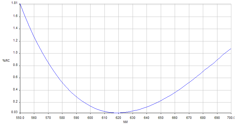
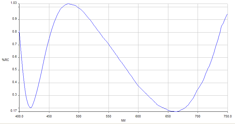
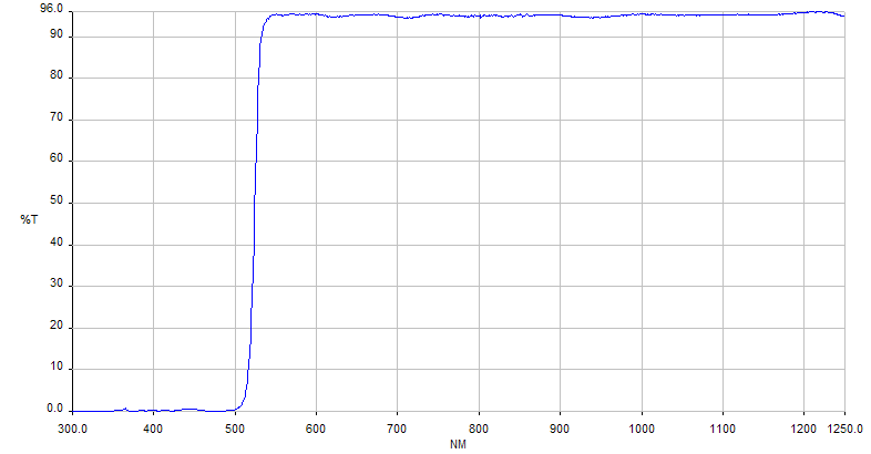
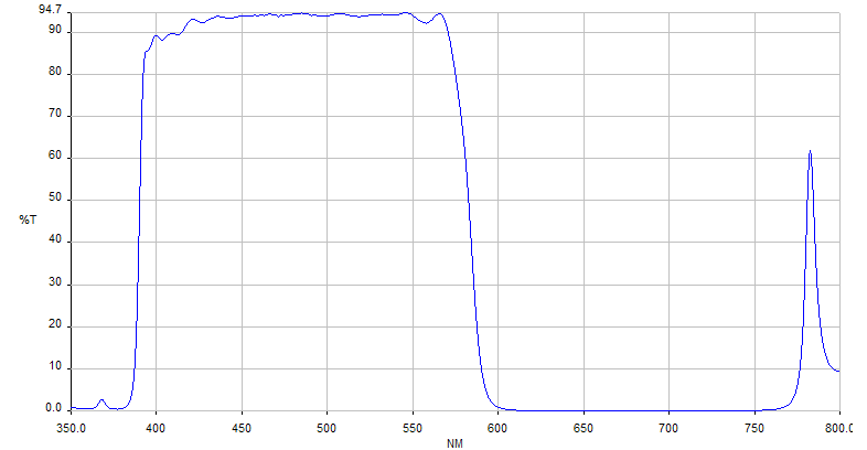
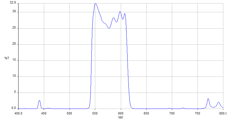
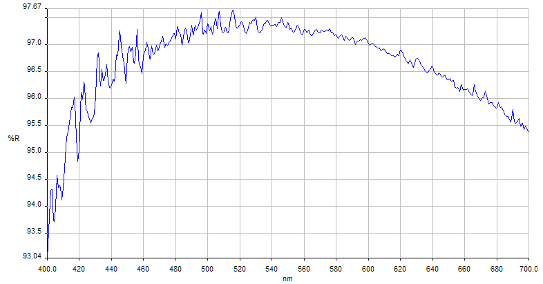
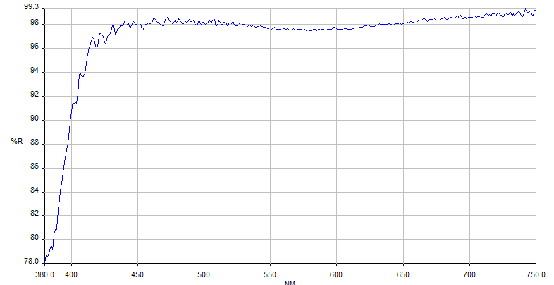
Other coatings are available upon request


